Industrial automation has become a critical component of modern manufacturing, driven by the increasing demand for efficient, cost-effective, and high-quality production processes. By reducing manual intervention and human error, automation has proven to enhance overall productivity, safety, and scalability across a wide range of industries.
At the heart of several industrial automation systems is “Ladder Logic,” a widely used programming language designed specifically for programmable logic controllers (PLCs). Developed in the 1960s, Ladder Logic emulates the behavior of electromechanical relay circuits, today, Ladder Logic has become the backbone of industrial automation with its simple, intuitive graphical format and powerful capabilities.
In this first article of our “Foundations of Industrial Automation” series, we will introduce the concept of Ladder Logic and its functions. We will explore real-world automation applications with Ladder Logic, the reasons for its global popularity, and how you can adopt Ladder Logic to automate your industrial processes.
Jump to Section:
Ladder Logic Functions
Automation and Real-world Examples
Step-by-step guide to automate your industrial process with Ladder Logic
Why you should Implement Ladder Logic? (Advantages)
Understanding the Basics of Ladder Logic:
Ladder Logic is a sophisticated and universal PLC programming language with a broad range of applications – from automating traffic lights at an intersection (switching between red, yellow, or green lights) using a pre-set Timer, to automating complex industrial machines and processes (such as sorting, batching, routing, packing, etc.).
To understand how Ladder Logic works, let us consider a classic electric circuit connected to start a Motor (figure). From the figure, it is clear that the electric current is passing from input rails to a Motor via a switch. Now the same circuit can be redrawn in a different way (figure b), with two vertical lines representing the input power rails and stringing the rest of the circuit between them.
Both these drawings have a switch and motor switch connected in series and depict that the motor receives electric current when the switch is closed. The second figure is called the ladder diagram and is more intuitive and self-documenting. A ladder drawing does not require a skilled electrical engineer to interpret. This ease of interpreting and troubleshooting industrial operations from the drawing is why Logic draws are popular.

Ladder Logic – Functions:
Similar to series and parallel connections in an electric circuit, a Ladder drawing contains Logic Functions (AND, OR, IF, NOT, and THEN) to depict a circuit. Contacts in a horizontal rung, i.e., in series, represent the logical AND operations (see the drawing below). AND function implies that for there to be an output, both input A and input B have to occur, i.e., input A “AND” input B contacts have to be closed. Similarly, the alternative paths provided by vertical paths from the main rung of a ladder diagram, i.e., paths in parallel, represent logical OR operations (second figure).


Programming Ladder Logic Drawings to PLCs:
Now that you have understood Logic drawings, Ladder is nothing but a series of Logic Drawings drawn in a sequence that is later programmed to a PLC using the software. Once programmed (using RSLogix 5000 software (for Allen-Bradley PLCs) and TIA Portal (for Siemens PLCs)), these PLCs start working autonomously to control industrial operations.
Read More: IoT, IIoT, Industry 4.0, and Industrial Automation: Myths, Similarities & Differences
Now let us understand how a real-world Ladder Logic program works. See the GIFs below (courtesy: SolisPLC). The first figure depicts that when Condition 1 fails (switch in open condition), the current flow from Left to Right is shut off, and the Output (ex: motor) is not energized.

The second figure represents a Switch in Closed condition, the current reaches the motor to energize.

While representing the exact (above) flow of current with an Electric Circuit Drawing can be difficult, Ladder Logic Diagrams depict this information in a much simpler way. Therefore understanding the visual representation ladder is easier for engineers and technicians to program PLCs.
To draw a Ladder Logic or to program a Ladder Logic to a PLC, IEC IEC 61131-3 prescribes certain conventions. These conventions are simple and intuitive to follow:
- Vertical lines represent the power rails, with power always flowing from the left-hand rail across a rung.

- Each rung represents one operation in the control process.
- Ladder diagrams should always be read from left to right and top to bottom. The PLC scans in this order and repeats the process in a cycle. The end rung is marked with “END” or “RET” to indicate the return to the start.

- Each rung must start with an input or input and must end with at least one output. The term input is used for a control action, such as closing a switch’s contacts, and as an input to the PLC. The term output is used for a device connected to the output of a PLC, e.g., a motor.
- Electrical devices are shown in their normal condition. Thus a switch that is normally open until some object closes it is shown as open on the ladder diagram. A switch that is normally closed is shown closed.
- A particular device can appear in more than one rung of a ladder. For example, we might have a relay that switches on one or more devices. The same letters and/or numbers are used to label the device in each situation.
- The inputs and outputs are all identified by their addresses. The notation used depends on the PLC manufacturer
Once you understand the conventions, refer to the following image to understand an industrial process using Ladder Logic programmed on a PLC using RSLogix 5000 (for Allen-Bradley / Rockwell Automation PLCs). Here, Motors 1 and 2 are automated to start after a time delay, using the Timer function of Ladder Logic:

Now that you have understood how Ladder Logic works, let us explore further the other functions of Ladder Logic used to sequence and automate complex industrial processes:
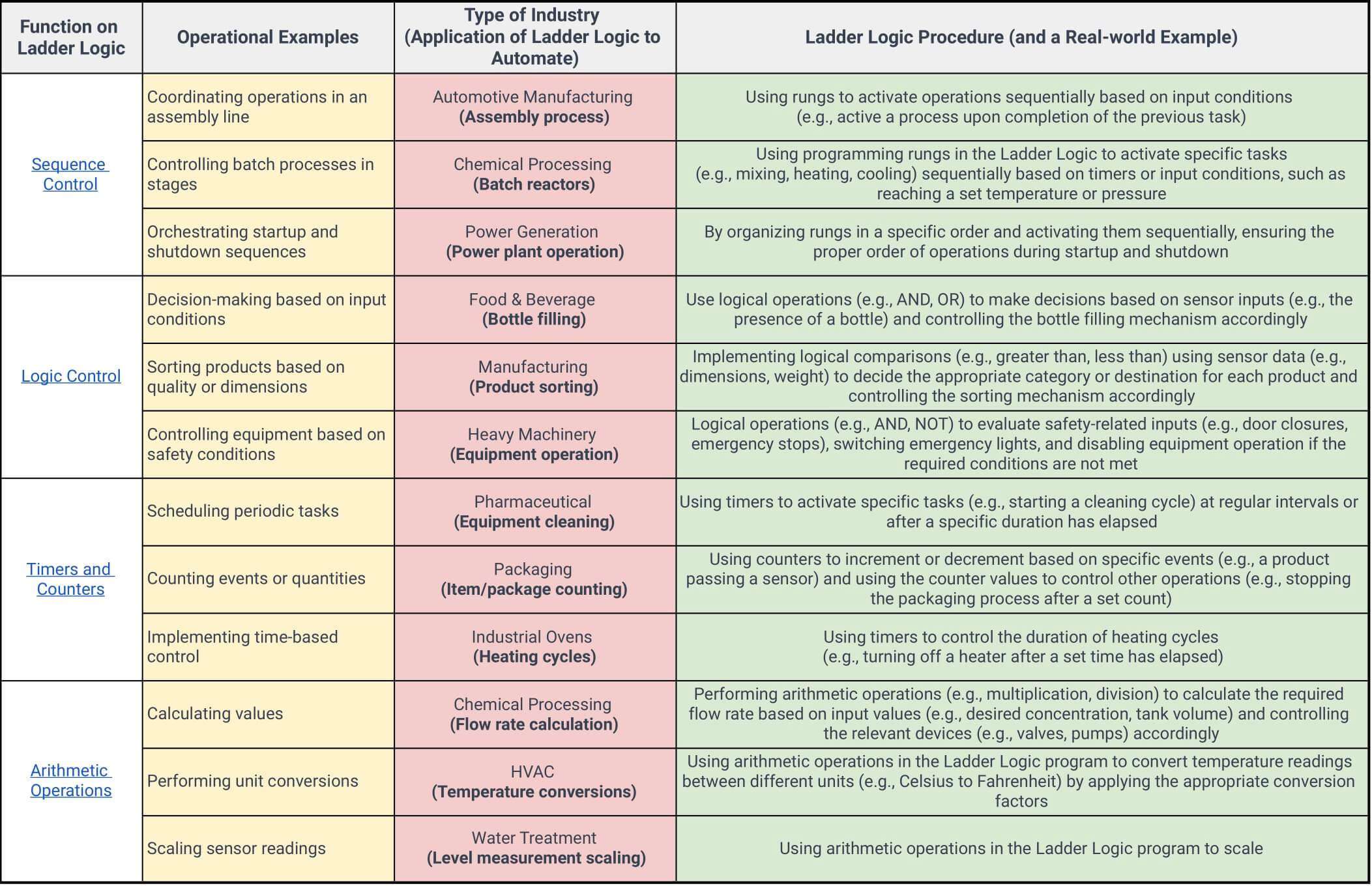
Ladder Logic – Automation and Real-world Examples (Table):
Ladder Logic uses combinations of the following functions (as required) to effectively control PLCs, which in turn manage various aspects of industrial automation processes. The Four primary functions of Ladder Logic are
- Logic Control: AND, OR, IF, NOT, and THEN conditions, used to control the functioning of machines based on specific conditions. For example, a machine may only operate if certain safety measures are in place, such as the activation of an emergency stop button.
- Timers and Counters: Timers and counters control processes that require precise timing or need to keep track of the number of cycles completed. This could include controlling the duration of an operation, such as heating an object for a specific period or counting the number of items produced on an assembly line.
- Arithmetic Operations: Arithmetic operations, such as addition, subtraction, multiplication, and division, to calculate values needed for process control. For instance, it can compute the average temperature in a facility by taking multiple readings and dividing the sum by the number of readings.
- Sequence Control: Managing the order of operations in a process, ensuring that each step is executed in the correct sequence. For example, in a bottling plant, the bottles must be cleaned, filled, capped, and labeled in a specific order to ensure a smooth production process.
Other functions such as Data processing, Signal processing, and PID control are used to manage sensor data from sensors, convert sensor data into digital values, and maintain the controls at a set parameter value.
Read More: Gas to Charging Stations: Innovation, Opportunities, & Challenges for EV Charging Infrastructure
Now, let us see the Ladder Logic functions applied to real-world scenarios. The following table provides an overview of Ladder Logic functions used in the industry to automate and sequence operations:
Why is Ladder Logic Critical for Industrial Operations?
- Standardization: IEC 61131-3 standard defines a common set of programming languages for PLCs, including Ladder Diagram (LD). Since the language is standardized, it is simpler for engineers and technicians to work with PLCs from different OEMs (such as Siemens, Allen-Bradley, or Mitsubishi, without engineers needing to re-learn), leading to widespread adoption.
- Ease of operation and troubleshooting: Ladder Logic’s graphical format is intuitive and closely resembles the ladder diagrams used in traditional electromechanical relay systems, making it easy for engineers and technicians to understand and adapt to.
- Compatibility with other programming languages: Ladder Logic can be combined with other IEC 61131-3 compliant programming languages, such as Structured Text (ST) or Function Block Diagram (FBD), and provides flexibility to design and implement automation systems. For instance, while Ladder Logic can be used for simple tasks like starting and stopping motors, Structured Text or Function Block Diagrams can handle more advanced tasks, such as data processing and advanced control algorithms.
- Flexibility and scalability: Ladder Logic programs can be easily modified and expanded to accommodate changes in the industrial process, such as adding new equipment or upgrading existing machinery. This makes it a versatile solution for a wide range of applications.
These practical advantages have contributed to its popularity across industries, making Ladder Logic a popular choice for engineers to automate industrial processes with PLC.