Journal Bearing Monitoring In Sheet Metal Rolling Lines
A technical review of journal-bearing monitoring in sheet metal reduction lines, connecting roll force, viscosity, lubricant feed condition, oil cleanliness, temperature, vibration, and maintenance action.
Sheet metal rolling lines place bearing decisions inside a process problem. The bearing is not an isolated component on a bench; it supports a roll neck while the stand reduces strip thickness, absorbs roll separating force, and runs through changing speed, coolant, lubricant, strip grade, reduction schedule, and thermal condition.
For industrial leaders, the maintenance question is therefore not simply, “Is the bearing hot?” A better question is: has the journal bearing retained a stable lubrication condition while roll force and process state are changing?
Why journal bearings are different
Rolling-element bearings communicate many defects through characteristic vibration frequencies. Journal bearings behave differently. The shaft journal rotates inside a stationary sleeve, and under normal operating speed the surfaces are separated by a hydrodynamic lubricant film. At startup, shutdown, inadequate supply, excessive load, or degraded lubricant condition, the system can move toward boundary or mixed lubrication.
This distinction matters. A journal-bearing programme should not be copied directly from a rolling-bearing programme. The signal stack must include bearing load, speed, lubricant feed pressure, feed temperature, flow, viscosity, oil cleanliness, bearing metal temperature where available, shaft displacement or vibration, and the maintenance action attached to each watch condition.
Technical literature on journal bearings emphasizes the lubricant film as the protective mechanism. A practical review in Machinery Lubrication notes that journal bearings operate in boundary lubrication mainly during startup and shutdown, while normal operation forms an oil wedge and full hydrodynamic film. The same review reports that common minimum oil-film thicknesses in midsized industrial equipment are often in the 5 to 75 micron range, and that viscosity grade selection depends on speed, temperature, and load.
Standards context for a rolling-line bearing programme
The standards context should be used as a measurement discipline, not as a shortcut to universal alarm values.
| Standard | Where it helps | How to use it in this case |
|---|---|---|
| ISO 17359 | Condition monitoring programme setup | Define failure mode, criticality, measurement method, review cadence, and action ownership. |
| ISO 13373-1 | Vibration condition monitoring procedures | Specify transducer location, attachment, operating state, data collection, and whether monitoring is continuous or periodic. |
| ISO 20816-3 | In-situ vibration evaluation for many coupled industrial machines above 15 kW | Use as broad machine vibration context, not as the sole diagnostic basis for journal-bearing distress. |
| ISO 3448 | Industrial lubricant viscosity classification | Record the selected ISO viscosity grade and compare in-service viscosity against the bearing and oil-system requirement. |
| ISO 4406 | Solid-particle contamination coding | Track cleanliness so abrasive contamination is visible as an oil-condition risk, not only as a later bearing symptom. |
| ISO 14830-1 | Tribology-based monitoring and diagnostics | Treat oil analysis, hydraulic fluids, synthetic fluids, and greases as condition-monitoring evidence. |
| ISO 7902-3:2026 | Hydrodynamic plain journal bearing operational parameters | Use permissible film-thickness, temperature, and specific-load context with OEM design data. |
For rolling-line assets, these standards should be treated as a measurement contract rather than a universal alarm table. The plant-specific watch and alarm bands still need the bearing geometry, OEM design basis, lubricant grade, baseline history, operating temperature, roll-force envelope, and maintenance response path. That discipline is precisely what makes the comparison useful: the public article can state the decision logic, while the plant baseline defines the final trip values.
Reference instrumentation for lubricant and vibration evidence
The measurement stack should be physically credible. A rolling-line review should connect oil condition, lubricant-feed behaviour, and shaft or housing response rather than treating each signal as an isolated dashboard tile.
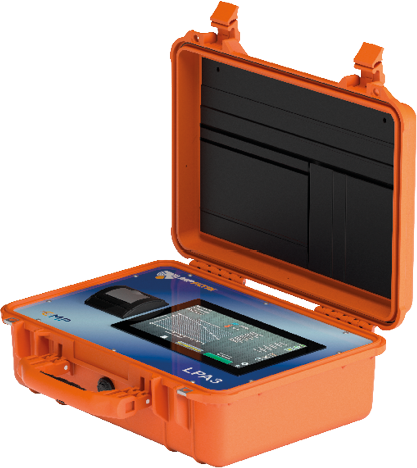
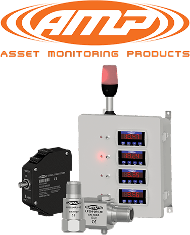
MP Filtri’s LPA3 is an example of a portable particle analyser used for hydraulic and lubrication-fluid health checks, including live trend analysis. CTC’s AMP Line 4-20 mA hardware is an example of continuous machine-health instrumentation with loop-powered vibration sensor options. These images are included as reference instrumentation categories, not as procurement recommendations.
What the process line changes
In a reduction stand, a bearing trend must be interpreted against the same process window that produced it. A viscosity change during low-load idle operation does not carry the same implication as a viscosity change during peak roll force. A temperature rise after a heavy reduction schedule does not carry the same diagnostic weight as a temperature rise during steady, repeatable production. A single manual oil sample can be valid and still miss the shape of the event.
The minimum useful signal contract should include:
- Roll stand, roll side, drive side or operator side, and bearing support position.
- Reduction schedule, strip speed, strip grade, roll force, and operating state.
- Lubricant grade, feed pressure, feed temperature, flow, return temperature, and filter condition.
- Oil cleanliness code, viscosity trend, water or particle evidence, and sampling location.
- Vibration or shaft-motion measurement point, unit, sampling interval, and baseline band.
- The inspection or shutdown-planning action when the trend reaches watch, investigate, or alarm state.
The video shows this sequence deliberately: the process line first, the roll-neck bearing second, the signal comparison third. That order matters because the bearing signal is only meaningful when the process load path is visible.
Evidence from rolling-mill literature
A useful industrial case appears in Bo Sun and co-authors’ 2016 paper, A Method of Feeding Conditions Monitoring of Journal Bearing in Tandem Cold Mill. The authors describe a monitoring system installed on the back-up roll journal bearing of stand 4 in a 1420 mm tandem cold mill at Baoshan Iron & Steel. The system measured hydrodynamic lubricant feed pressure, feed temperature, and flow close to the bearing inlet.
Several details make the case valuable for plant teams:
| Reported detail | Why it matters |
|---|---|
| Monitoring point close to bearing inlet | It reduces the ambiguity caused by pressure loss, filter clogging, regulator issues, leakage, or temperature difference between pump room and mill stand. |
| Pressure sensor range of 0 to 1 MPa and temperature range of 0 to 100 deg C | The instrumentation was selected around the lubricant feed condition rather than a generic dashboard variable. |
| Data acquisition at 10 Hz | The system preserved transient lubricant-feed behavior rather than relying only on occasional inspection readings. |
| Back-up roll bush diameter reported around 785.8 mm and lubricant viscosity at 40 deg C around 220 mm2/s | The case is clearly a heavy rolling-line journal-bearing application, not a small generic bearing example. |
| No unexpected online burning accident on the monitored stand after RHMS application, with 22 h downtime saved in 2014 compared with 2013 and reported benefits of $630,000 | The reported benefit came from earlier warning and decision timing, not from claiming that monitoring removes all mechanical risk. |
The authors also note a boundary condition that should be preserved in any serious reading of the case: the equipment monitored one journal bearing in one stand, and the monitoring system needed expansion for broader coverage. That caveat is important. Good condition monitoring is not a universal claim; it is a bounded proof loop.
How manual checks and online monitoring should coexist
Manual inspection should not be portrayed as naive. A technician can find oil leakage, abnormal smell, seal damage, blocked drains, unusual sound, heat, vibration, and housekeeping problems that a narrow sensor may miss. The weakness of manual inspection is not human competence; it is sampling density.
Use the two methods together:
| Evidence source | Strength | Limitation | Best action |
|---|---|---|---|
| Manual route | Physical context, leaks, heat, sound, visible contamination, inspection judgement | Sparse in time | Use for verification and corrective work scoping. |
| Oil laboratory sample | Viscosity, contamination, wear debris, chemistry | May miss short transient behavior and depends on sampling discipline | Use for root-cause evidence and lubricant-management decisions. |
| Online feed monitoring | Pressure, temperature, flow, and trend shape near the bearing | Needs correct sensor placement and data-quality ownership | Use for early warning and watch-state review. |
| Vibration or shaft-motion trend | Mechanical response under load | Needs operating-state context | Use to connect oil condition with machine behavior. |
The strongest programme is not manual versus online. It is manual plus online, interpreted through operating state.
Failure evidence and reported benefits
Public failure reporting often becomes visible only after consequences are large. The East Palestine derailment is outside a rolling mill, but it is a useful public caution about bearing detection timing: the NTSB concluded that a defective wheel bearing caused the derailment and hazardous-material release, and that the crew did not receive the hot-bearing warning until the overheated bearing was about to cause axle failure.
Rolling-line literature provides the more directly relevant industrial case. In the Baoshan tandem cold mill study, the monitoring system was introduced to prevent online burning accidents by observing lubricant feed conditions near the journal bearing. The authors reported that the monitored stand avoided further unexpected online burning accidents during the reported period and documented measurable downtime and economic benefits. Those numbers should be read as a reported case result, not as a generic promise.
The Industry Digits view
Journal-bearing monitoring in rolling lines should begin with a precise asset question.
If the answer is no, the first project should be narrow. Select one stand, one bearing position, one lubricant system, and one maintenance action path. Establish the baseline under known roll force and strip conditions. Then decide whether the proof loop deserves expansion.
For a broader rotating-asset programme, connect this article with the Bearing & Rotating Asset Monitoring blueprint and the Critical Asset Monitoring service path.

Lokesh Chennuru writes Industry Digits field notes for industrial decision makers, focused on automation, IIoT, condition monitoring, predictive maintenance, and industrial AI.
Connect on LinkedInQuestions industrial leaders ask about this
Why is journal-bearing monitoring different from rolling-bearing monitoring?
A journal bearing supports a roll neck under changing roll separating force, speed, lubricant, and strip condition, so the signal stack must include load and lubrication state. It should not be copied directly from a rolling-bearing program.
What signals matter for journal bearings in rolling lines?
Roll-force context, lubricant viscosity and feed condition, oil cleanliness (ISO 4406), temperature, and vibration read against operating state. The real question is whether lubrication condition stays stable as roll force changes.
How should a first journal-bearing monitoring program be scoped?
Narrowly: one stand, one bearing position, one lubricant system, and one maintenance action path, with a baseline established under known roll force and strip conditions before deciding whether to expand.
Ready to turn signals into a maintenance decision path?
Book a 30-minute consultation and we will map the fastest useful condition-monitoring or automation win.